Electrical Circuits
During this unit, we learned extensively about electricity and how it works and behaves in circuits. We took weeks, first building circuits with thick wires and alligator clips with potentiometers and lightbulbs and the likes, before graduating to the exceptionally smaller, neater, but trickier breadboards.

Breadboard; photo courtesy of
|
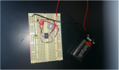
Completed breadboard circuit by Daria, Richard, and me. Notice the black 555 timer chip in the center and the illuminated LED light... the light blinks on and off when the circuit is closed!
|
Physics Concepts:Circuit: a complete loop of conductive material with a power source
Resistors: poor conductors that reduce voltage (ex: light bulbs)
Voltage: power that electricity gives off, push/pull of electricity, pressure or Potential Energy difference
Series circuits: draws less electricity because each additional bulb is extra resistance. Voltage changes, but current remains the same throughout.
Parallel circuits: draws more electricity because as the number of bulbs increases, the resistance in turn goes down. Parallel circuits are independent, unless they're in series with another set of parallel circuits.
Kirchoff's 1st Rule: "The total current out of a node equals the total current into the node."
Breadboards: vertical rows are connected in the outermost columns on both the left and right side; in the center columns, horizontal rows are connected
Ohm's Law: Voltage = Current x Resistance
Resistors are banded with different colors to indicate the strength of the resistor. The code goes as follows.
|
0 Black
1 Brown 2 Red 3 Orange 4 Yellow 5 Green 6 Blue 7 Violet 8 Gray 9 White 0.1 (+/- 5%) Gold 0.01 (+/- 10%) Silver |
First band: 1st digit
Second band: 2nd digit Third band: # of zeros Fourth band: tolerance (gold or silver) |
This unit was extremely rigorous. It lasted weeks, and demanded a lot of concentration and "figuring out", especially as we got to breadboards. It was extremely easy to get everything jumbled up into an inscrutable mess, so it really reinforced the idea of neat organization. Along with the programming, this unit took a lot of will to stay focused and on-task for me, I do not seem to find electricity naturally intriguing but in the end, it helped me learn that although what is being taught seem asinine and boring, it proves to harbor invaluable resources for future reference. Anything is worth learning; you never know when you may need it! I think our group collaborated really well together, and I think that we did a good job in the end of persevering to reach our goals, which all in all is a really satisfying feeling. This project was extremely educational, really. I hardly knew a thing about electricity; I knew what it was, what it can and does do, and why it does it, but I never understood the way electricity does the things it does, and now I can manipulate it do do things I want. Along with coding, this was just a really helpful project.
